
Desert Online General Trading LLC
Dubai, United Arab Emirates
Desert Online General Trading LLC
Dubai, United Arab Emirates

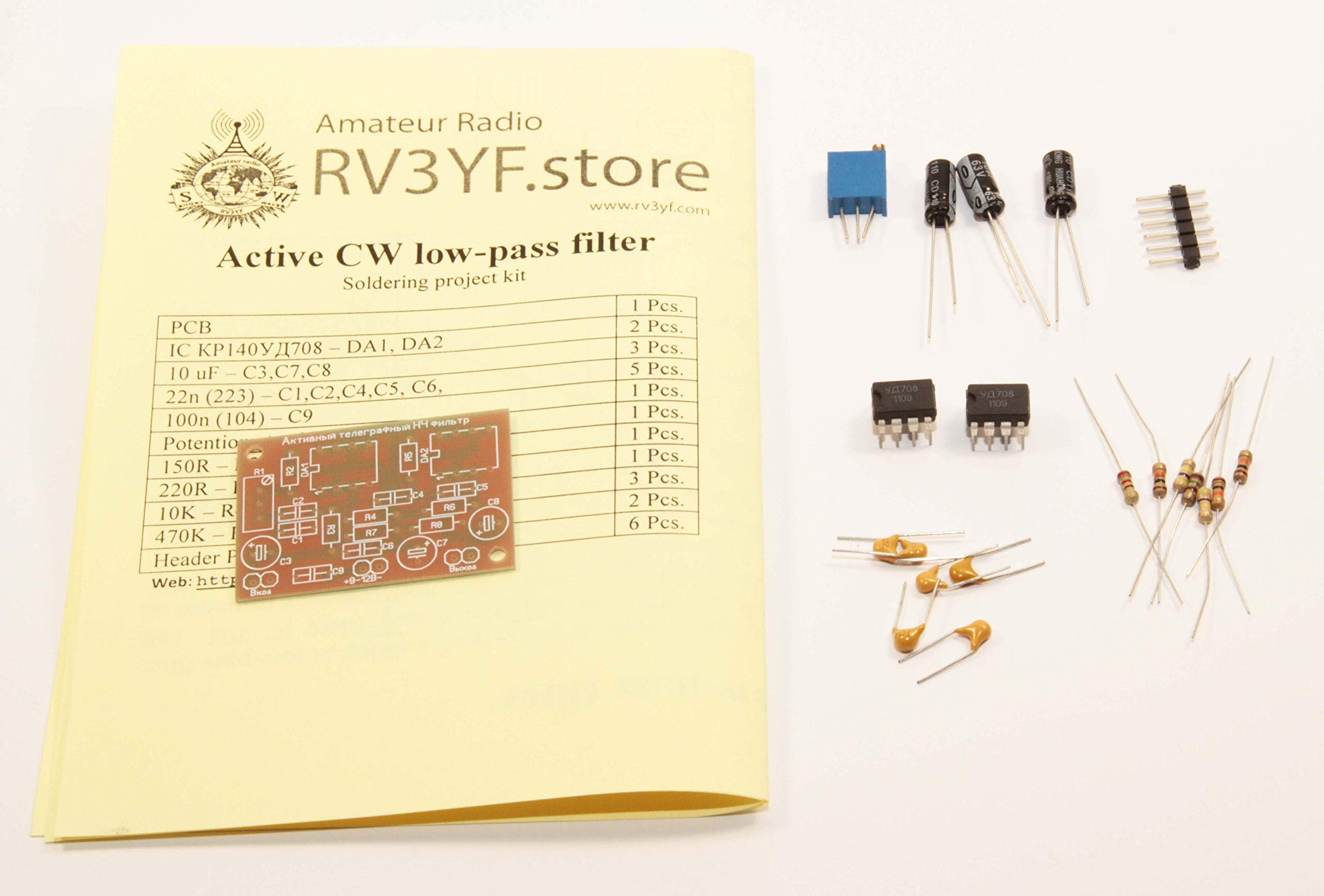
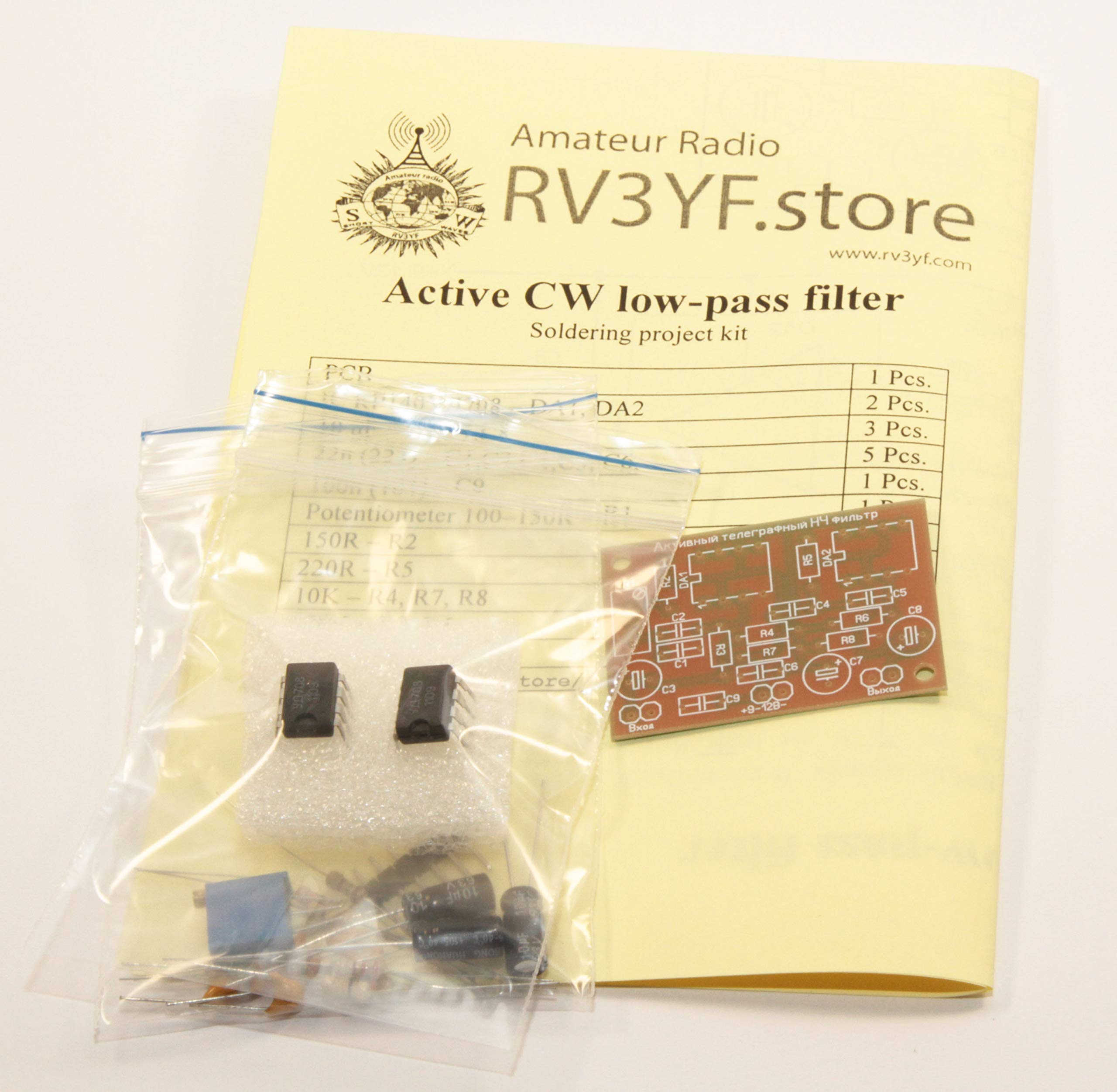
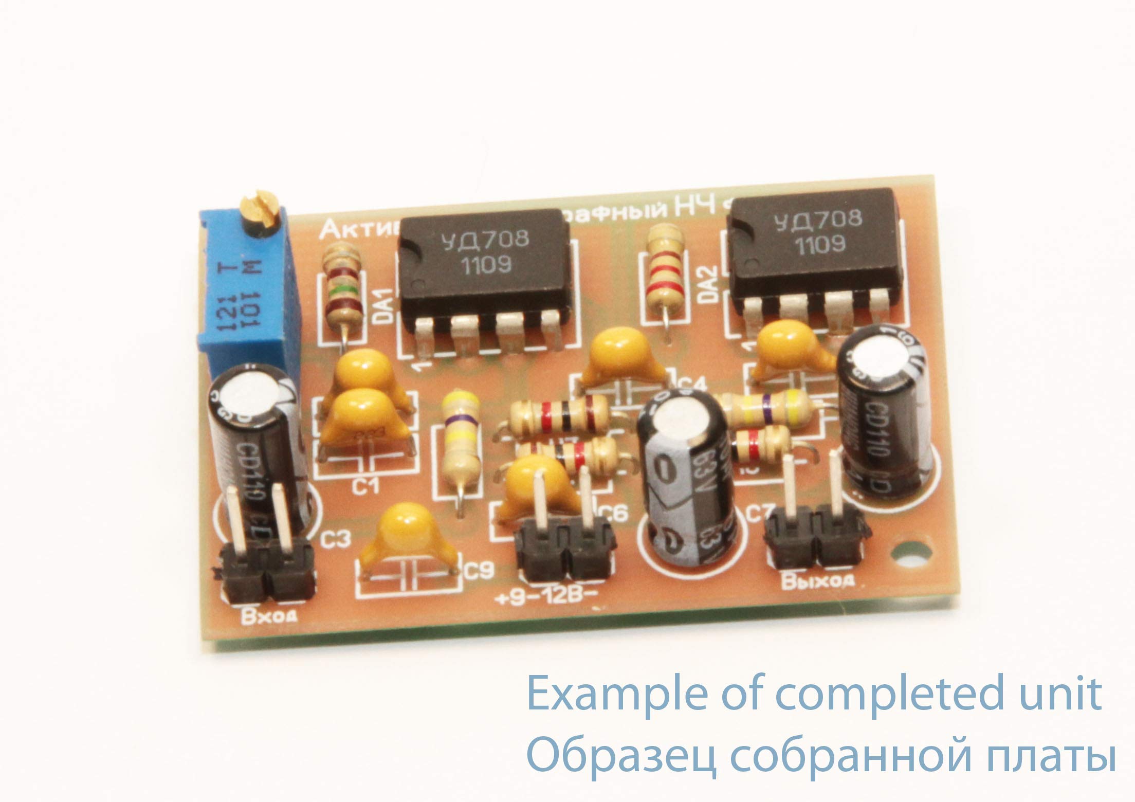
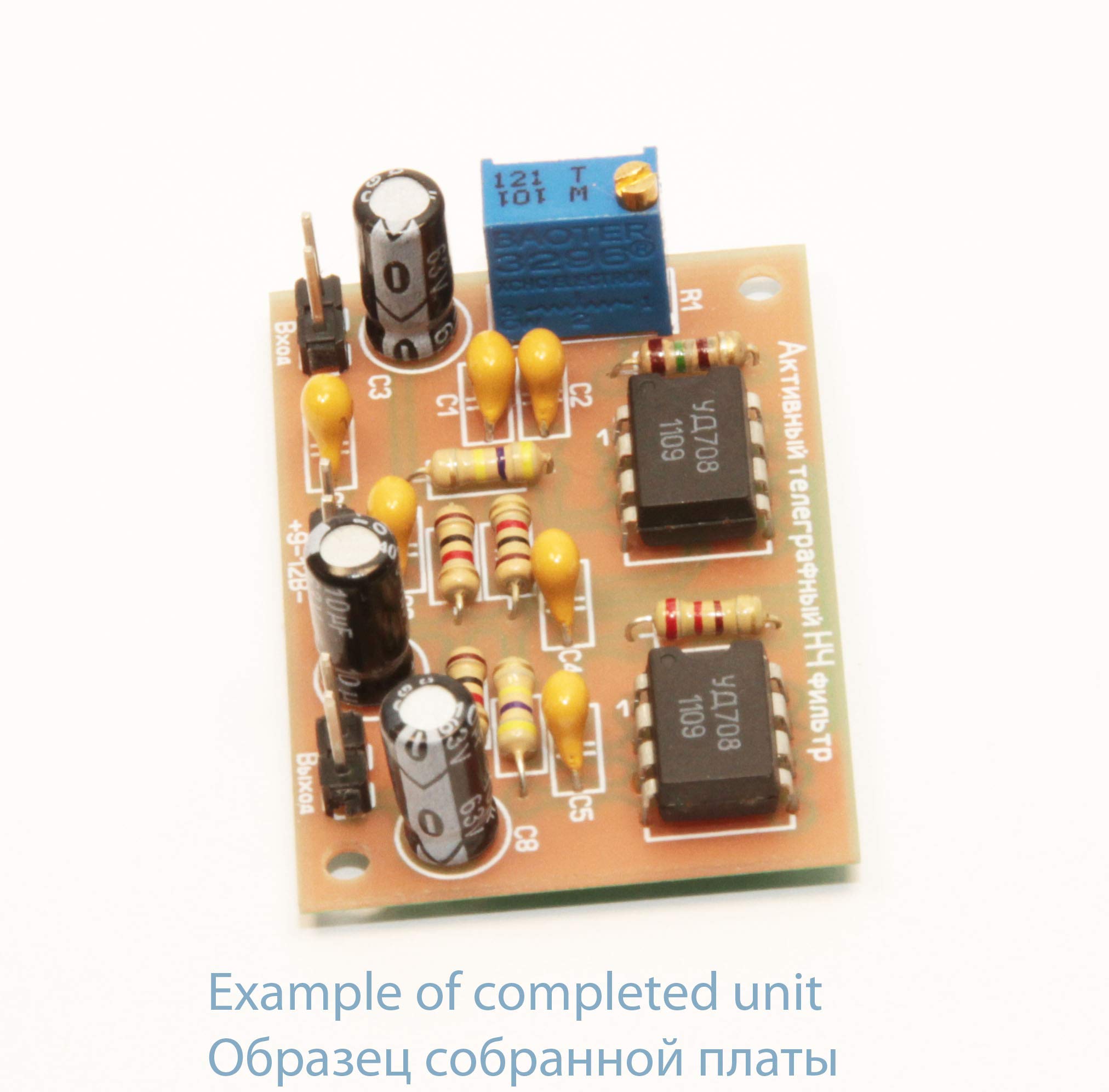
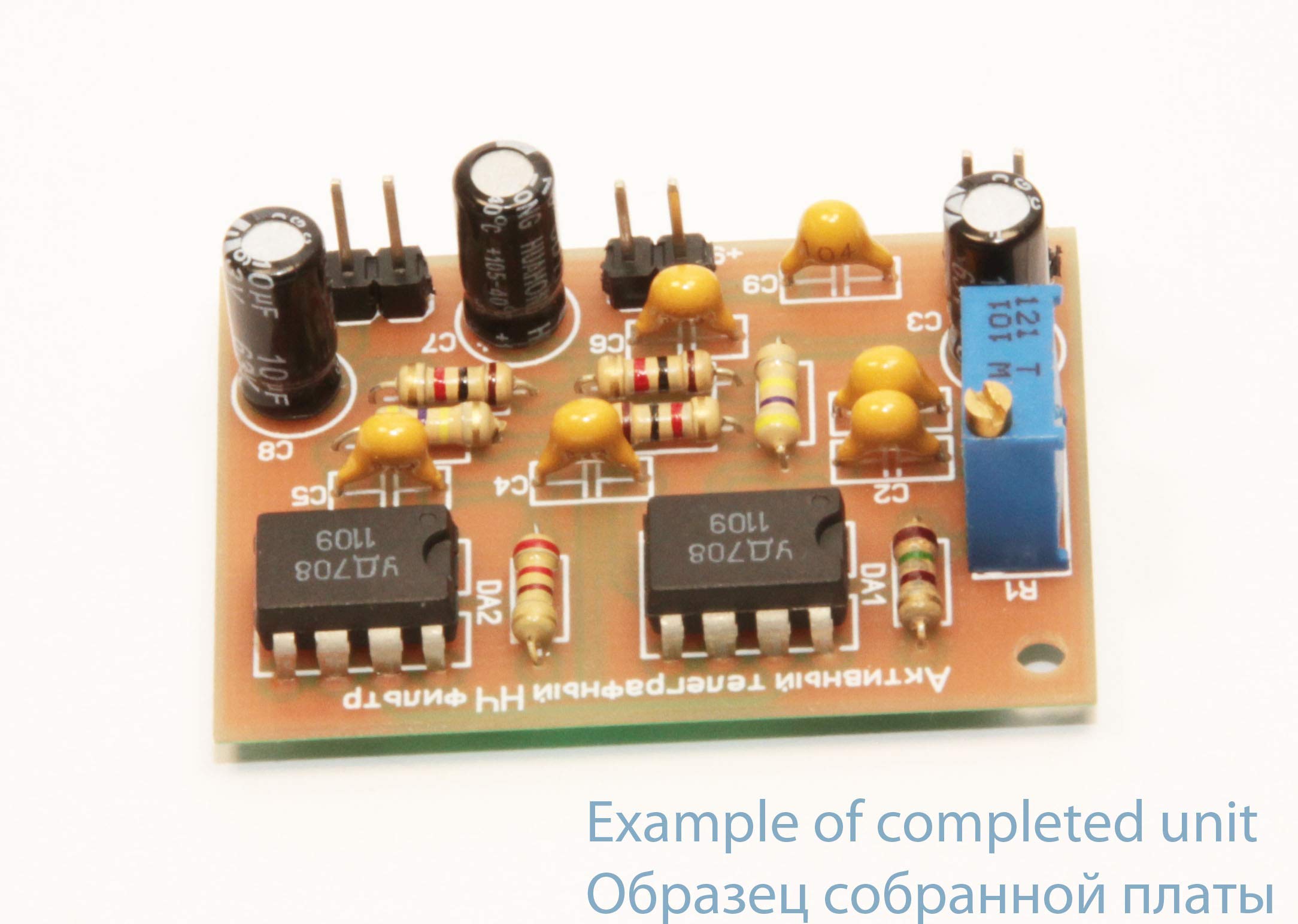
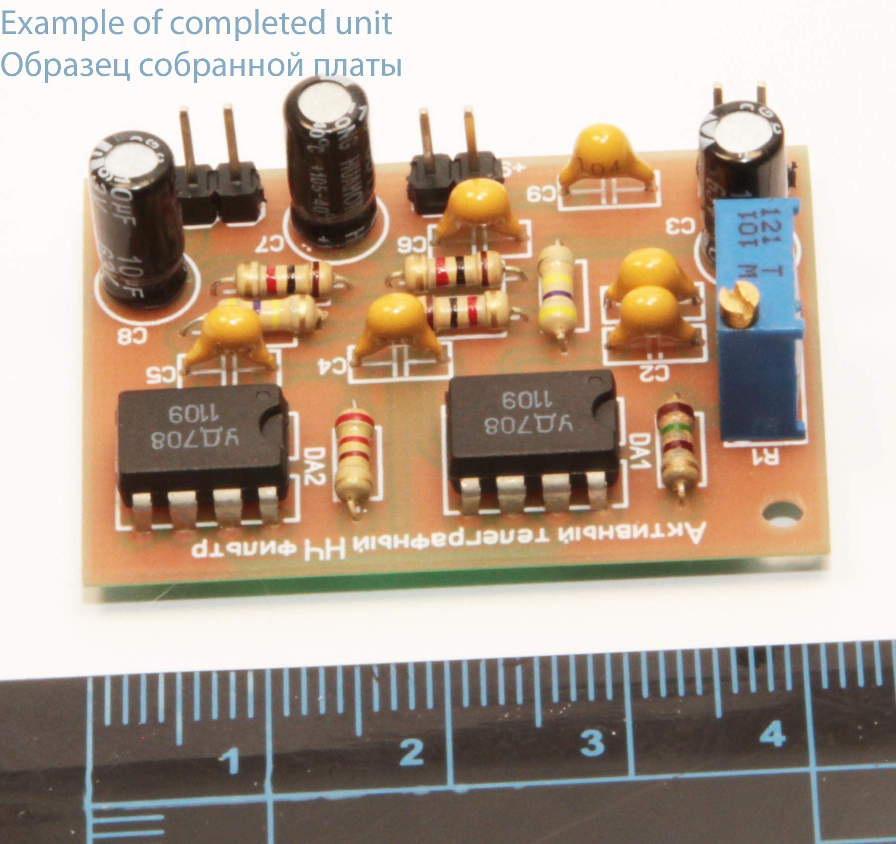
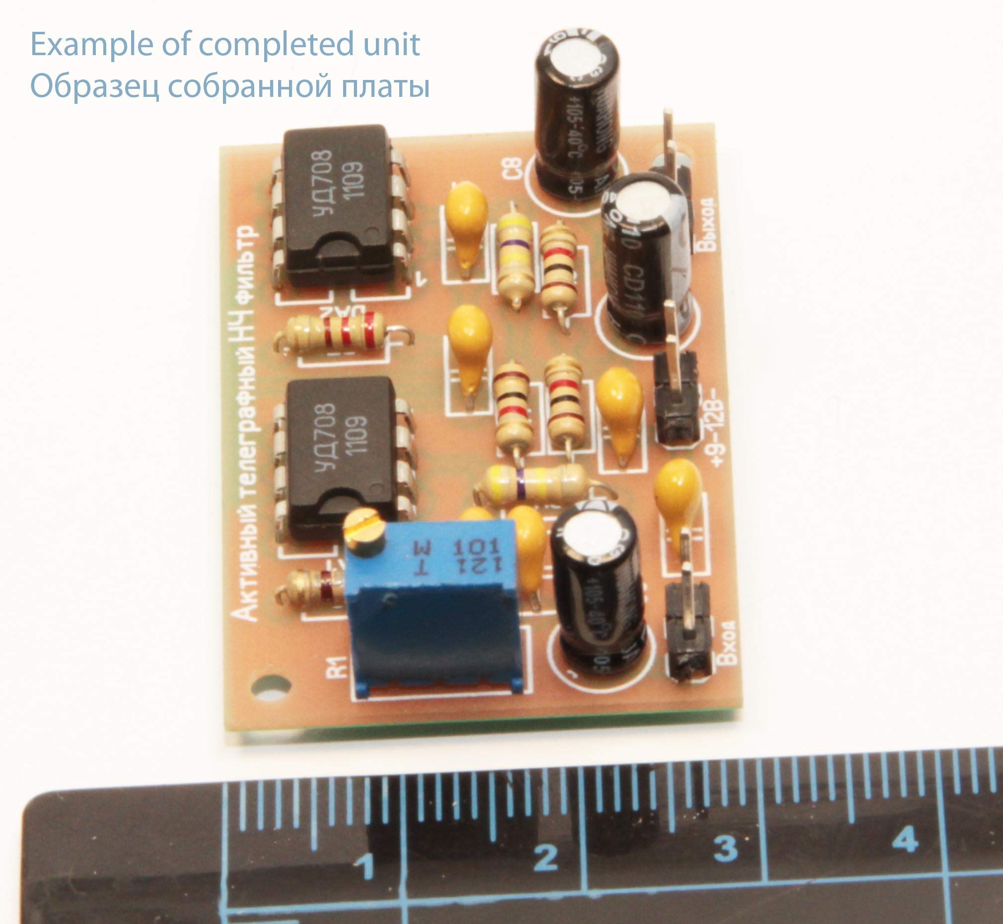
The proposed filter is designed to receive Telegraph signals. It consists of a series of low-pass filter (LPF, DA1) and high-pass filter (HPF, DA2), which are built on operational amplifiers IC 708. The parameters of the frequency-determining elements of the filters are chosen so that the frequency response of both filters has a noticeable rise at the quasi-resonance frequencies F0 (see Fig.). Since the LPF and the HPF are connected in series, together they form a bandpass filter. The frequency of the quasi-resonance of the HPF is fixed and equal to 800 Hz, and the frequency of the quasi-resonance of the LPF can be changed by the tuning resistor R1. Each filter has a quasi-resonance frequency transmission coefficient of about 15. If set frequency 750 Hz of quasi-resonance LPF by R1, the filter as a whole will have a form, which is shown in Fig.2 at the bottom left. The transmission coefficient in the maximum frequency response (corresponds to about 770 Hz) will be about 160. If it is set to 700 Hz, the frequency response will have the form shown in Fig. at the bottom right. The transmission coefficient in the highs of the frequency response will be about 60. In most cases, the second option of setting the filter, which provides a wider bandwidth, is preferable, since too narrow-band filters tend to "ring", require very stable heterodynes in the equipment of both operators. The filter is powered from a source with a voltage of DC 9-12 V. The constant bias on the non-inverting inputs of operational amplifiers (half the supply voltage) sets the voltage to R7, R8.
Trustpilot
Hace 3 semanas
Hace 2 semanas