Description
🚀 Elevate Your Projects with Cutting-Edge Clarity!
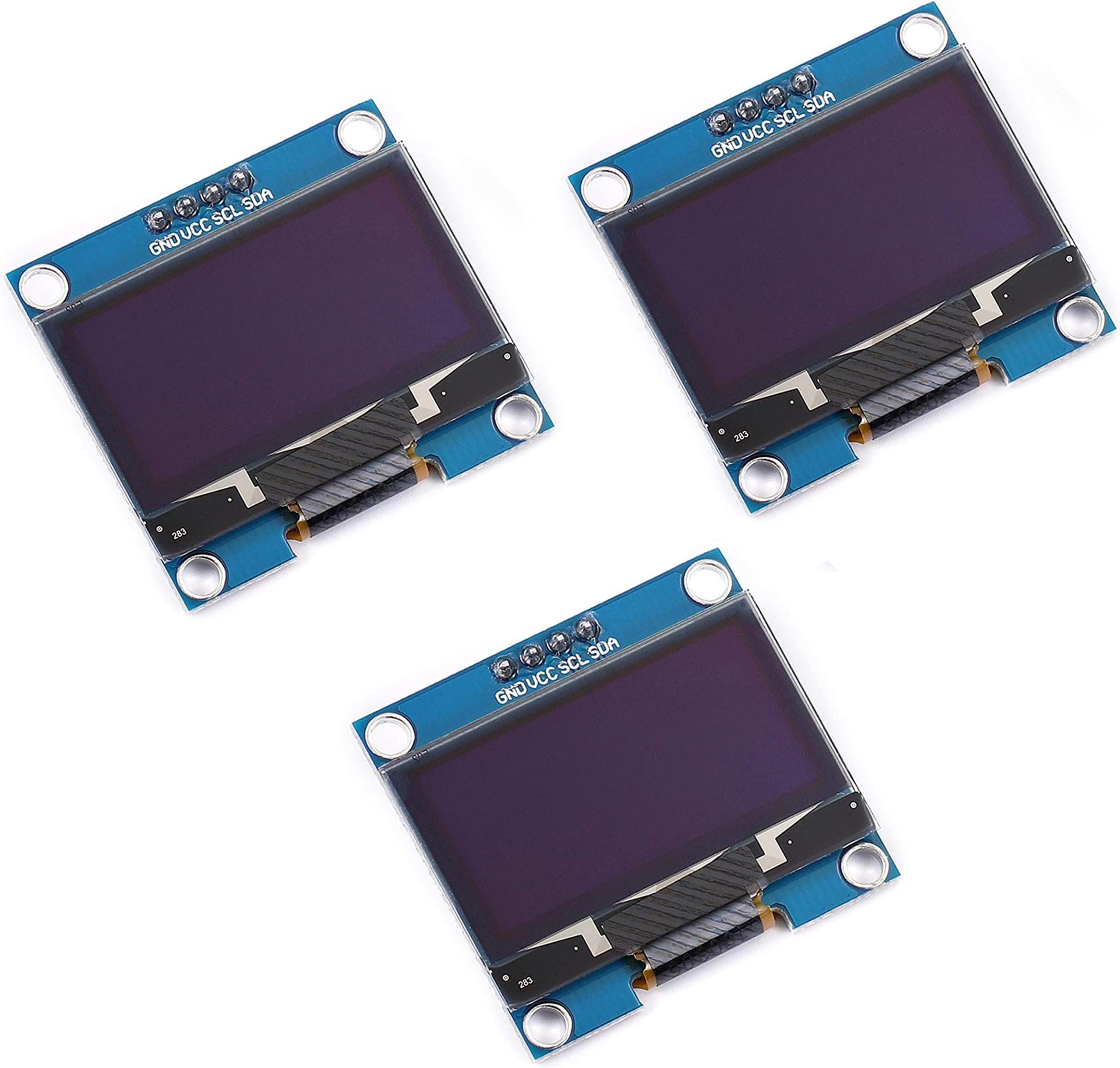
- COMPACT DESIGN - Sleek dimensions (35.4mm x 33.5mm x 4.3mm) fit perfectly in any project.
- VERSATILE COMPATIBILITY - Seamlessly integrates with both 3.3V and 5V systems for hassle-free setup.
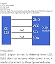
- MULTIPLE OPERATING MODES - Choose between 3-wire SPI, 4-wire SPI, or IIC for ultimate flexibility.
- ULTRA WIDE VIEWING ANGLE - Experience visuals from any angle with a stunning 160°+ view.
- ROBUST TEMPERATURE TOLERANCE - Designed to perform in extreme conditions, from -30°C to 70°C.
The Teyleten Robot 1.3 inch OLED Display Module features a 128x64 resolution and ultra-wide viewing angle, making it perfect for various applications. With low power consumption and compatibility with multiple operating modes, this compact display is ideal for Arduino and Raspberry Pi enthusiasts looking to enhance their projects.