Desert Online General Trading LLC
Dubai, United Arab Emirates
Desert Online General Trading LLC
Dubai, United Arab Emirates


⚡ Power your ESP32 projects with precision and style!
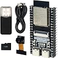
The Freenove Breakout Board FNK0091 is a dedicated terminal block shield designed exclusively for Freenove ESP32 and ESP32-S3 series boards. It features multiple 5V and 3.3V power outputs capable of delivering up to 3A, an independent GPIO status LED for real-time signal monitoring, and a user-friendly pin header layout with 2.54mm pitch. Ideal for professionals seeking reliable, plug-and-play hardware expansion with comprehensive technical support.
| Brand | FREENOVE |
| Series | Freenove Breakout Board |
| Item model number | FNK0091 |
| Operating System | Embedded |
| Item Weight | 2.82 ounces |
| Package Dimensions | 4.92 x 3.31 x 1.02 inches |
| Color | for ESP32 / ESP32-S3 |
| Processor Brand | Freenove |
| Number of Processors | 1 |
| Computer Memory Type | SRAM |
| Manufacturer | Freenove |
| ASIN | B0CD2512JV |
| Date First Available | July 28, 2023 |
Trustpilot
2 months ago
1 month ago